
 English
 Arabic
 Chinese
 Dutch
Dutch Finnish
 French
 German
 Hebrew
 Hindi
Hindi Italian
 Japanese
 Korean
 Polish
 Portuguese
 Russian
 Spanish
 Swedish
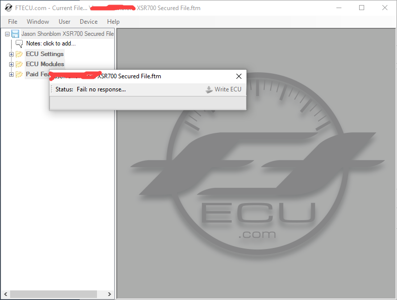
Status: Fail: No Response error when trying to connect.
 jshonblom@live.com
Posts: 6Verified User
jshonblom@live.com
Posts: 6Verified User
in XSR 700
I am attempting to flash my ECU for the first time. My repro steps are
- Click the Write ECU button.
- A Prompt asks me to turn Bike On, I do It
- I get asked it I would like to apply license to ECU, I click yes. The software marries license to ECU
- I get Asked to turn bike off, I do so, and click OK
- I get a message saying Writing ECU: turn Key on, I do so, and click OK
- The status goes to connecting, and then it goes to Status: Fail: No Response
I have went pack through my installation a few times, ensuring the pins were pushed in. I have moved the ground wire all over the bike, but still have the same issues. The current ground wire location is the recommended spot under the tank, which I have sanded down a bit. My multi meter reads 12 so it seems like a solid spot.
Any thought on whats going on, pretty frustrating?
Comments
Fail no response means that there is a hardware issue, the software is pinging the ECU but not getting any response. Please check all your connections carefully.
You can use the hardware test in the software. Go to Help > Test Interface > Inputs
Don't pay attention to the colored dots, you're only interested in the numbers that are shown. The Red wire is #1, the Orange wire is #2, the Yellow wire is #4, and the Black wire is GND.
With everything connected but with no power to the ECU, acceptable inputs are 0, 10, 20, or 30. If you don't see these numbers, the sum of the second digit indicates the bad wires. For example, if you see "36", the 6 indicates that Orange #2 plus Yellow #4 have no continuity.
With everything connected and the ECU powered, acceptable inputs are 6, 16, 26, and 36. If you don't see these numbers, look at the second digit. If you get 1, 3, 5, or 7, that indicates a possible bad connection with the Red wire. If you see 2, that indicates a bad connection with the Yellow wire. A 4 indicates a bad Orange wire connection. And a 0 indicates a bad power supply to the ECU; check the positive 12V and common GND wires.
Hey Kent, I used the hardware test in the software. When everything was hooked up and the key was off I got the number 30. See screenshot:
When I turned on the Key and powered the ECU I received a 36. See Screenshot:
I went through the same steps as I did before, and received the same Fail No Response Error.
What Next?
-Jason
Please give us your ECU part number, and file number you are attempting to flash.
My ECU Part number is 2RC-8591A-20 (2018 xsr700)
Here is a screenshot of the File in the device tab the blotched out part is my name. It is a custom, secured file from 2 Wheel Dyno Works. I inquired with them on why the file reflects 2RC-8591A-00 (which is for a '15 FZ-07) and not 2RC-8591A-20. They mentioned it is a bug/glitch in the FTECU software and that all FZ/MT/XSR700 Files will show a -00 in the devices tab, and that it is indeed for the 2RC-8591A-20 ECU.
I also tried to use the Public file: 2018 MT-07 - 2RC-8591A-20(US) - Unrestricted.ftm file, but found that I received the same Fail No Response Error
Thanks,
-Jason
Can you try the stock XSR700 file from the tuning suite to see how that turns out?
The only stock xsr700 file is a (CA) file, so I tried the 2018 MT-07 - 2RC-8591A-2-(US) - StockECU.ftm file and it also did not work. See Screenshot:
Thoughts?
Please check your bike-side harness for voltage. Pull off the protective cap, and use a voltmeter to check these combinations:
With key/ignition to ON, Orange wire to a GND should read 5V, Yellow wire to a GND should read 5V, Red wire to a GND should read 12V. Next, jumper the Red wire to the Yellow wire; if you hear the fuel pump priming, there is an issue with the harness. If not, then it's good. Then jumper the Red wire to the Orange wire; again, if you hear the fuel pump priming, then there's an issue with the harness. If not, then it's good.
Let us know what you find.
I'm having a very similar issue. Has this been resolved? If so what is the solution?
I just checked the voltage of the bike side harness and have found that the Orange to GND is 5V, Yellow to GND is 5V, but the voltage of the red to GND is 0.1. This seems like the issue, I have tried to seat the Red pin further by pushing the wire deeper using my fingers as well as sliding a paper clip in next the wire to push the metal pin down. Do you have any tips on this? I still do not get a voltage reading on the red wire. The resistance reading on the wire is 0.1-0.2.
Thoughts? I pretty much just want to ride, should I be looking at buying the Bench side harness as this method is not working so good?
Yes, your red power wire is not making any connection. If you look at the face of the connector, can you see any of the pin visible? You should be able to see at least some metal in the tiny hole where the red pin is inserted on the opposite side.
Also, are you sure you have the red wire pin inserted in the correct pin hole? It shouldn't be that difficult to insert the pin and get a good connection.
Please perform all the hardware checks previously mentioned.
This was a case of user error. I reviewed the installation steps once again and found that I had put the orange pin in six spaces from the 32 side rather than six spaces from the 17 side on the middle row. I was tunneled in on making sure the pins were in rather than in the right spot. Once I moved the orange pin to the correct spot I was able to write to the ECU no problem. Thank you for your help during this process.
-Jason
I Know this is solved but it is important to note that the red wire on your bike-side harness is not power. You would not expect to get voltage from it normally but providing voltage to this wire by crossing it to yellow or orange should prevent the fuel pump from priming.
I'm experiencing this issue now. I went over the bike-side hardware installation with FTECU Support (fantastic by the way) and determined that everything was hooked up properly, and the Interface Test displayed the correct numbers as well. Being completely baffled by this, and desperate to tune my 2018 XSR700, I now have the bench-style ECU Flash kit. Unfortunately, I still receive the "Status Fail: no response..." message exactly as described in the very first post here. I'm still working with Support, but if anyone has any ideas on how to fix this I would be eternally grateful.
Travis, please send an email to sales@ftecu.com regarding your issue.